
For this lab, you must have the tetrahedral meshes and the surface and collision meshes of the pig liver and ribs generated in the previous lab. If you have not yet generated the files you can download the meshes.zip file.
Loading data in Sofa
The goal now is to load the liver data that we generated in the previous TP. From the file beam_implicit.scn we will replace the topology of the regular grid with a mesh of the liver.
Replace the RegularGrid component with the MeshVTKLoader components that will load file .vtu you generated during the previous TP. It’s important to note that you need to choose the volume mesh (tetrahedral) since the main node will describe the mehcanical model on which FE computations will be performed.
Add the component TetrahedronSetTopologyContainer that will contain the tetrahedral topology. To use these components, specify the file that will be loaded by MeshVTKLoader using the filename attribute and give a name to loader with the name attribute. Then specify the source of the topology (TetrahedronSetTopologyContainer component) at using the src=”@loader” where loader is the name of the MeshVTKLoader component (be careful to add the @ in front of the loader).
Visual model
To add the textured visual model of the liver, we will add a sub-node that we will call Visual. In this subnode, we first need to load the .vtk file containing the visual model using the MeshVTKLoader component. As for the volume mesh we will now use the TriangleSetTopologyContainer to hold the triangular topology.
To visualize the triangular mesh add the following components that will show the texture liver-cyrrhosis.png on the model.
<MeshVTKLoader name="loader" filename="CHOOSE_THE_CORRECT_FILE" />
<TriangleSetTopologyContainer name="triTopo" src="@loader" />
<OglShader vertFilename="shaders/generalRenderingShader.vert" fragFilename  ="shaders/generalRenderingShader.frag" />
<OglShaderDefineMacro id="TRI_TEXTURING" />
<OglShaderDefineMacro id="TRI_TEXTURING_SINGLE_TEXTURE" />
<OglShaderDefineMacro id="PHONG" />
<OglShaderDefineMacro id="BUMP_MAPPING" />
<OglFloat2Variable name="scaleTexture" id="scaleTexture" value="50 50" />
<OglFloatVariable name="bumpFactor" id="bumpFactor" value="1" />
<OglTexture id="planarTexture" textureFilename="liver-cyrrhosis.png" textureUnit="1" repeat="true" />
<OglTexture id="normalMap" textureFilename="liver-cyrrhosis-NM.png" textureUnit="2" repeat="true" />
<OglShaderVisualModel name="visualModel" material="texture Ambient 1 0.8 0.8 0.8 1.0 Diffuse 1 1.0 1.0 1.0 1.0 Specular 1 1.0 1.0 1.0 1.0 Emissive 0 0.15 0.05 0.05 0.0 Shininess 1 100" />
Finally, add a BarycentricMapping between the mechanical mesh and the visual mesh.
We will add a visualization of the model of the ribs in the simulation. Add a second node (below Beam ) with the name Bones. The ribs will remain static, so there is no need to add time integration components nor mesh finite elements.
Inside the Bones node, create a textured visual node for the sides, and modify the file that will be loaded by the loader so that it points to the visual mesh of the ribs. Having no mechanical model, it is not necessary to use BarycentricMapping. Finally, modify the textureFilename attribute of the OglTexture components to load the data/bone_texture.png for the component with id planarTexture and data/bone_normalmap.png for the component with id normalMap .
Simulation without interactions
Adapt the modulus of young to match that of a medium pig liver that is about 3500 MPa, and the mass at 0.5 Kg. Add constraints to fix the model using the BoxConstraint component then select an area of fixed points in the center of the liver.
Note: You can use the shift+r key to show/hide the frame of the scene, and the box is visible by ticking behavior model. The frame is scaled with the scene so it does not show unit vectors. Finally, adapt the time step so that the simulation is as fast as possible while remaining stable.
Simulation of interactions
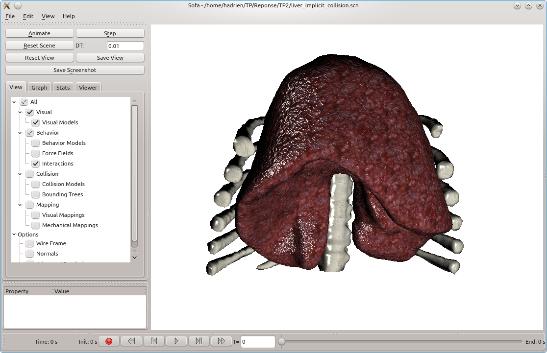
We will simulate the interactions with the coasts. Create a liver_ implicit_collision.scn file from the liver_implicit.scn file .
Collision meshes
At this point, both models are displayed, but no collision are detected between the two structures. For this purpose we need to add: 1) collision models 2) collision detection and 3) collision solver.
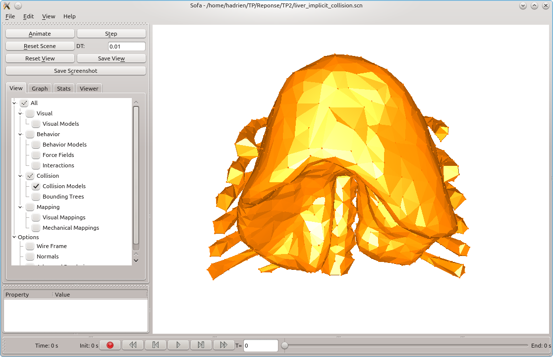
We will begin by adding the model of collision of the liver. Add a coarse mesh that will be mapped to the mechanical model. The principle is then very similar to the visual node. Add a node named collision, in which the loader will load the coarse mesh. To calculate mechanical forces to treat the contact, it will be necessary to add a MechanicalObject, and a BarycentricMapping. Finally, add the Triangle and Point components that calculate the collisions with these meshes.
Repeat for the ribs, but as the ribs are static, you will not use BarycentricMapping. Run the simulation, and check the collision tab to see the collision meshes in yellow.
Collision detection and response
Having no collision detection or collision solver in the scene, no interaction will be computed between the two models. For that, a set of component must be added in the main node of the scene:
<FreeMotionAnimationLoop />
<GenericConstraintSolver maxIt="100" />
<CollisionPipeline name="pipeline" depth="6" verbose="0" />
<BruteForceDetection name="detection" />
<CollisionResponse name="response" response="FrictionContact" />
<LocalMinDistance name="proximity" alarmDistance="5" contactDistance="0.1" angleCone="0.8" />
The first two components declare the collision solver, while the last four declare the detection method used. Finally, add the PrecomputedConstraintCorrection component inside the liver node, which makes it possible to apply the contact forces on the deformable model (it is not necessary to add this component for the ribs because they will remain static). This component will precompute the inverse of the initial matrix and use it as an approximation of the compliance matrix to solve the contacts. The first time you run the scene it will compute this matrix (that may take some time) and store it in a file. If you re-run the scene it will not compute the inverse anymore and directly use the file. However, if you change the mechanical parameters you will have to delete manually the file to force the re-computation of the inverse.